How to Install Carbon Fiber Arms with Zero Backlash Magnetic Joints on a Kossel Clear
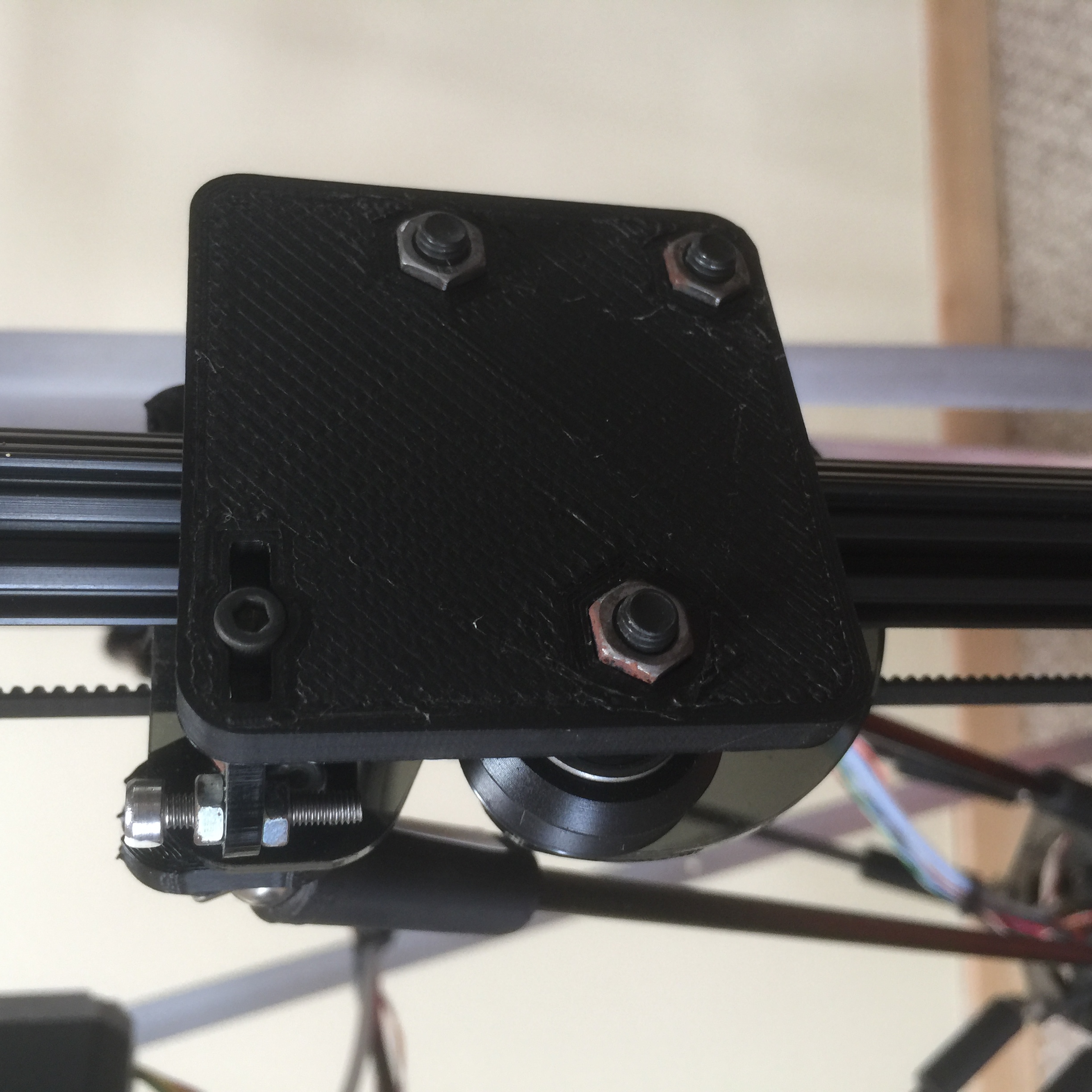
Outside of carriage.
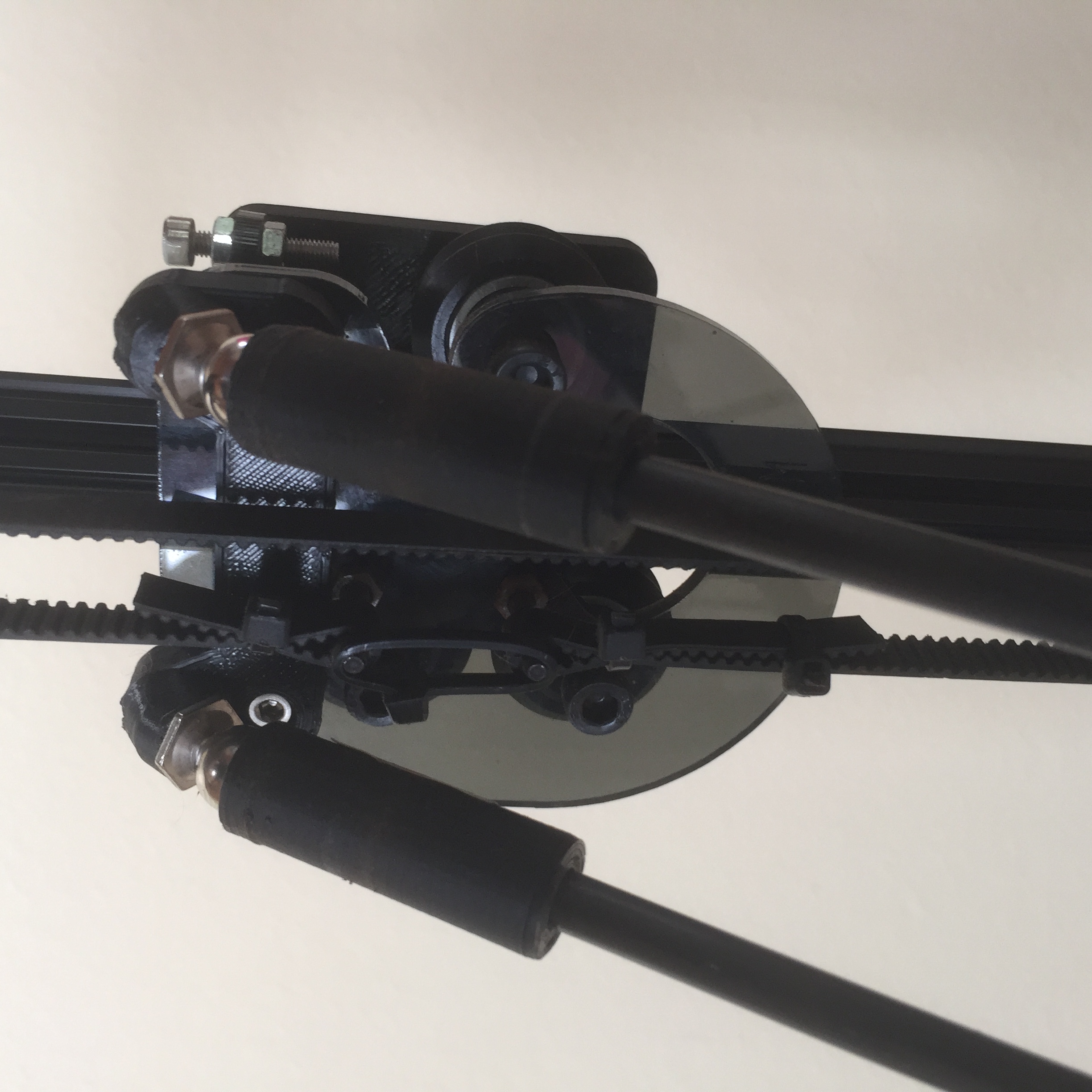
Inside of carriage.
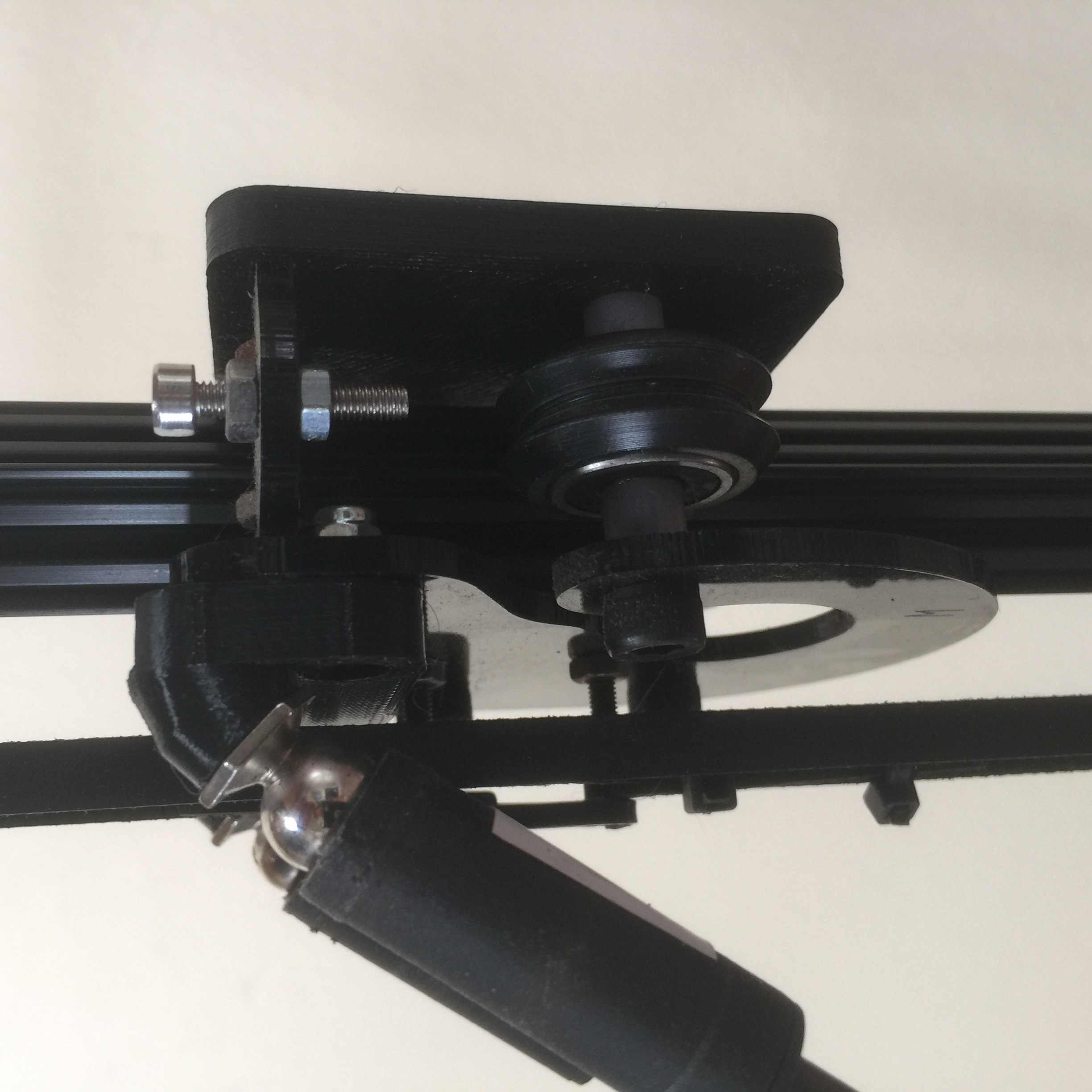
Side view, showing angled carriage adapters between
ball studs and acrylic.
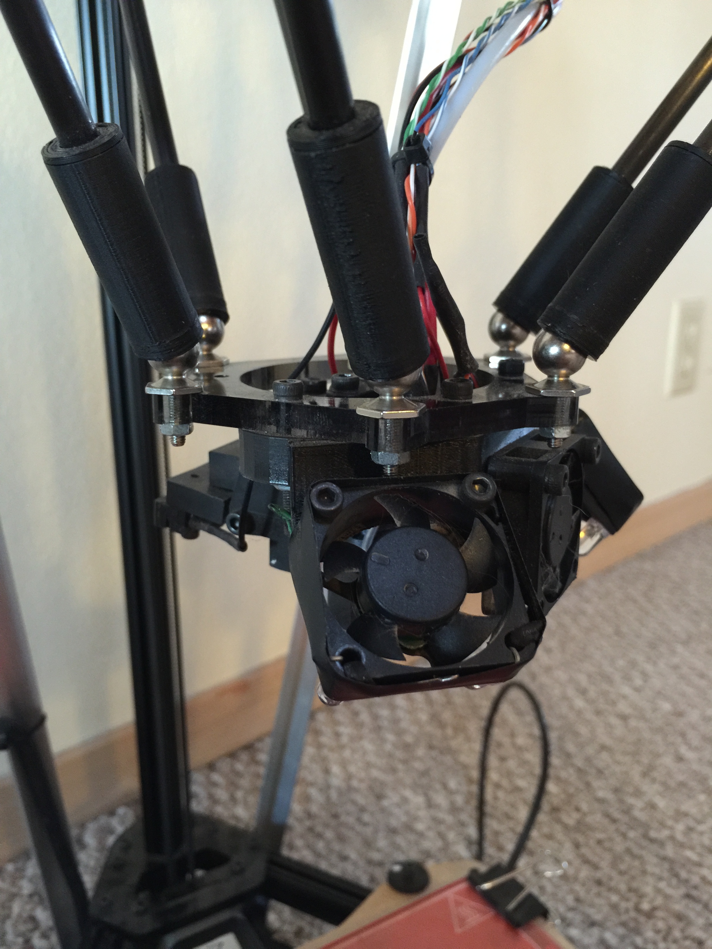
Effector with arms.
Carefully remove the old Traxxas joint arms from the effector and carriages.
If you are careful enough, you can do this while the carriages remain on your printer, but the acrylic carriages are a little bit brittle, and I accidentally snapped one of mine!
(I wasn’t careful enough the first time and accidentally broke one of mine. I temporarily taped it back together and it worked ok. Later I decided that wasn’t good enough, so I used the broken inside carriage as a template to drill three 3mm (or 1/8”) holes in an outside carriage, to replace it with.)
Install six of the ball studs on the effector. Use M3 nuts to fasten them. If you have nylock nuts, those would be ideal to use — they won’t work themselves loose over time. An alternative is to use a pair of M3 nuts tightened against one another on each bolt.
Install two ball studs into each of the three angled carriage adapters with nylock nuts, and then attach the angled carriage adapters to the inside carriage pieces using M3x8’s. Also install the new, stiffer outside carriage pieces.
Install the magnetic carbon fiber arms and write down the six lengths written on them. Later on you’ll need to know the average of those lengths for DELTA_DIAGONAL_ROD. I’ve carefully measured your rods using a large micrometer. Those numbers are the distances from the center of one ball at one end of a rod to the center of the other. Ideally, you can pair the two shortest rods together on one carriage, the two longest on another, and the two middle length ones on the last carriage.
Note: When you place your eye in the center of the top of your printer and look down, you should see that each pair of arms is parallel. If they aren’t, then detach the effector, rotate it by 60°, and reattach. You’ll be connnecting each pair of arms to the pair of adjacent ball studs which are the furthest apart, and which match the distance between the ball studs on the carriages.
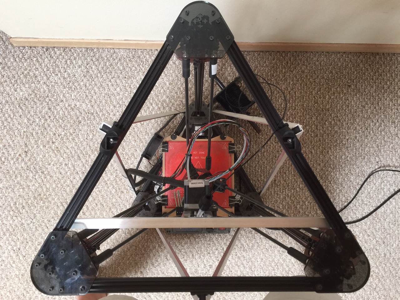
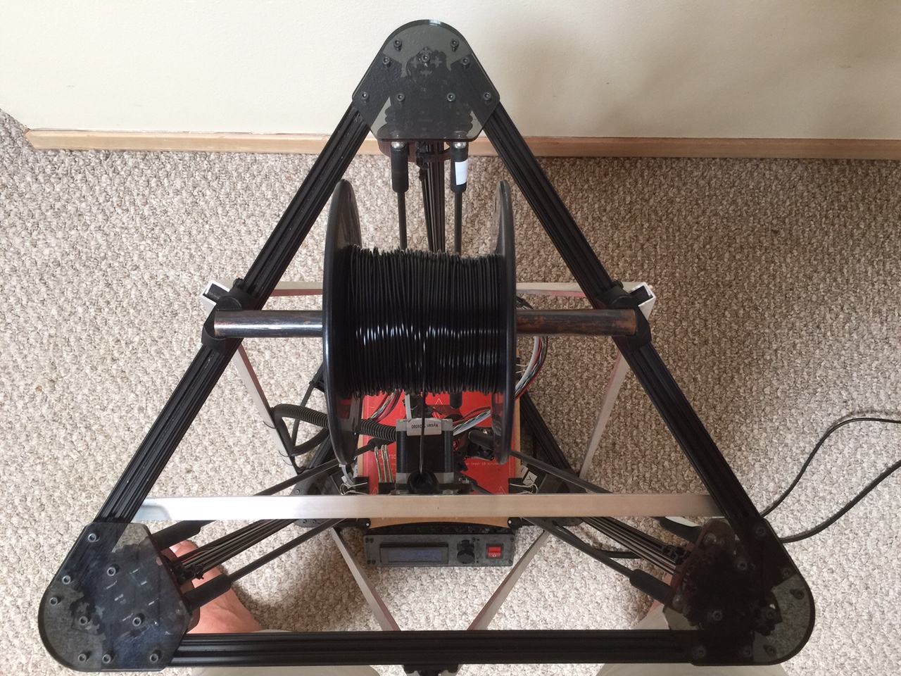
Here are two pictures of my modified Kossel Clear, showing the parallel arms when looking downward:
Looking down, with spool removed.
Looking down, with spool mounted.
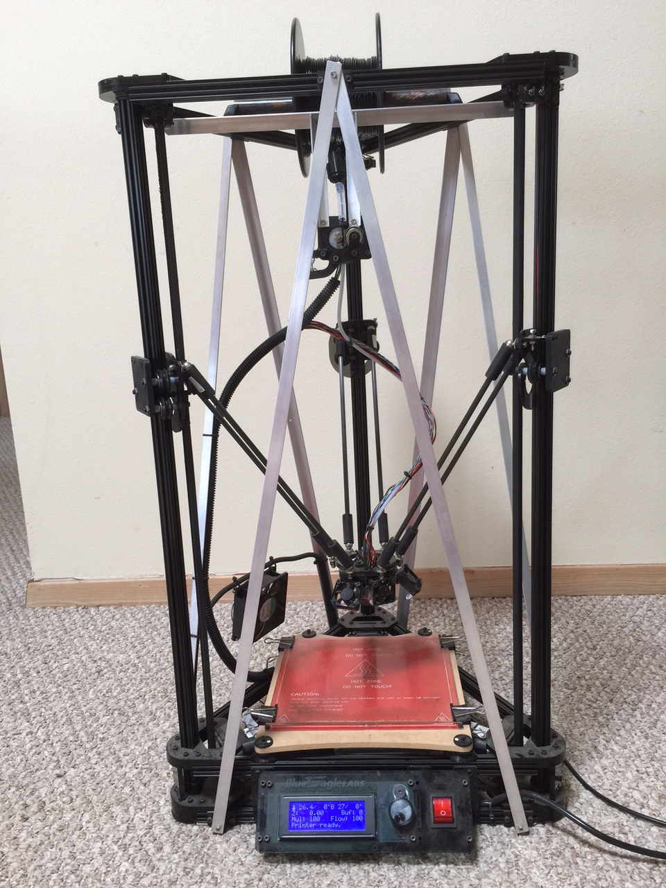
Front view.
Here are the STL files in case you would like to print them yourself:
Now you will need to recalibrate your KC in order to get the best performance out of it. Before this point, if your calibration was a little bit off, the slop in the system may have hidden it. Now you will notice smaller miscalibration problems, but there is a much easier technique for calibrating your printer to within a smaller margin of error than you’re probably used to.
I’ll assume that you’ve been using BEL’s version of Marlin.
Download and use this slightly modified copy of Rich Cattell’s version of Marlin, which I’ve named Marlin_RC_master:
Download ZIP
RC’s documentation is on this page:
Documentation
Take a moment to peruse the documentation to get an idea for some of the new parameters you can change in EEPROM and the new things you can do with it.
Note: You must compile Marlin (or Repetier) with version 1.0.5 of the Arduino IDE. For some reason the newer versions produce code which doesn’t work correctly!
Here is the page which has download links to all of the old versions, including 1.0.5: https://www.arduino.cc/en/Main/OldSoftwareReleases
Use the Arduino IDE to compile and upload the version of Marlin in Marlin_RC_master to your KC’s Arduino.
Use Pronterface to connect to your KC’s Arduino running the new software from Marlin_RC_master.
Here is an example:
Use the M502 command to load the default values from the code into EEPROM. (This prevents random values in your EEPROM from causing problems.)
Here is an example:
Use the M666 L command to list the new parameters in EEPROM, which you can now change without recompiling. After changing a parameter, home your printer (by clicking on the home button or with G28), and then you will be using the new parameter. You no longer have to recompile Marlin each time you want to change something!
Here is an example:
>>>M666 L
SENDING:M666 L
Current Delta geometry values:
X (Endstop Adj): 0.00
Y (Endstop Adj): 0.00
Z (Endstop Adj): 0.00
P (Z-Probe Offset): X0.00 Y0.00 Z-5.10
A (Tower A Position Correction): 0.00
B (Tower B Position Correction): 0.00
C (Tower C Position Correction): 0.00
I (Tower A Radius Correction): 0.00
J (Tower B Radius Correction): 0.00
K (Tower C Radius Correction): 0.00
R (Delta Radius): 160.00
D (Diagonal Rod Length): 288.00
H (Z-Height): 283.00
Use the command M666 R154.5 to set the value for Delta Radius to 154.5mm, which should be pretty close to the right value.
>>>M666 R154.5
SENDING: M666 R154.5
Use the M666 Dnnn command to change the value for DELTA_DIAGONAL_ROD. In step #4 above, I hope you wrote down and calculated the average length of the diagonal rods. This is the first place to use it. It should be close to 288±0.3mm.
On my printer, the average was 287.91mm, so I’ll use M666 D287.91
Here is an example:
>>>M666 D287.91
SENDING:M666 D287.91
If you’d like, you can use M666 L again to verify that the value has changed.
Now use the M500 command to save your changes to EEPROM:
>>>M500
SENDING:M500
echo:Settings Stored
The G30 E command is useful for checking how well calibrated your bed is. Flick your Z-probe down and use the G30 E command to probe your bed at seven key points and display a report.
Here is an example:
Now let’s calibrate your printer. Use the command G30 A Dnnn, where nnn is the value you entered for DELTA_DIAGONAL_ROD in installation step #4.
This tells your printer to run the new autocalibration sequence. It may take a while. In Configuration.h I set AUTOCALIBRATION_PRECISION to 0.05mm (50 microns). The G30 A Dnnn tells the printer to start calibrating itself, and to not change the Diagonal Rod Length. This makes calibration pretty quick. Mine calibrated in just 7 iterations.
Here is an example:
>>>G30 A D287.91
SENDING:G30 A D287.91
Starting Auto Calibration..
	Z-Tower			Endstop Offsets
	-12.1250		X:0.00 Y:0.00 Z:0.00
-12.3300	-12.2300	Tower Position Adjust
	-12.2450		A:0.00 B:0.00 C:0.00
-12.1950	-12.1900	I:0.00 J:0.00 K:0.00
	-12.1100		Delta Radius: 154.5000
X-Tower		Y-Tower		Diag Rod: 287.9100
Using diagional rod length: 287.91mm (will not be adjusted)
Iteration: 1
Adjusting Z-Height to: 293.25 mm..
.
.
.
Iteration: 7
Adjusting Endstops..
	Z-Tower			Endstop Offsets
	-0.0050			X:-2.07 Y:-2.12 Z:-1.80
-0.1100		-0.1000		Tower Position Adjust
	-0.0000			A:0.22 B:-0.16 C:-0.06
-0.0050		-0.0150		I:0.00 J:0.00 K:0.00
	0.0300			Delta Radius: 154.5000
X-Tower		Y-Tower		Diag Rod: 287.9100
Auto Calibration Complete
Issue M500 Command to save calibration settings to EPROM (if enabled)
When you have your printer calibrated to your satisfaction, then use M500 to save the new, optimized parameters to EEPROM.
I calibrate my printer once, and then use it for months, never having to recalibrate it (or use the old G29 command).
Now test your KC. I use a quick and simple calibration object, which is a square 100mm on a side. It takes less than 2 minutes to print. You can download the STL file from here. While printing it, I watch how the first layer goes down. Is it even all around? Is there anything I need to tune manually? Also I use inexpensive 150mm calipers to verify that the object is actually square, and that the sides are close to 100mm. In this case they turned out to be 100.35mm horizontally and 100.82mm vertically. I have no idea why it’s not perfectly square, but it’s within 1%, and that works for me!
Note: You can also use the G30 A command to automatically try to calibrate all of the parameters for your printer. This takes quite a bit longer than G30 A Dnnn. In practice, I have found that this does not work as well. It alters the Delta Diagonal Rod parameter significantly, which results in objects being printed either too large or too small.
I normally use RC’s Marlin together with Pronterface for calibration and then switch to using Repetier-Firmware with Repetier-Host for production, because Repetier’s print quality is much better, especially at high speeds and on small radius curves. If you would like to use Repetier, you can plug in the numbers which RC’s Marlin calculated in step #10 above using the table below.
The biggest difference between them is that RC’s Marlin measures the endstop offsets in negative mm, while Repetier measures them in positive steps. To convert, change the sign and multiply by the number of steps/mm.
Here is Repetier-Firmware 0.92.8 configured for a Kossel Clear: Repetier.zip
If you come up with any improvements to this configuration, please let me know!
My favorite feature is Z Babystepping, which uses the knob to finely adjust the Z-height, typically while printing the skirt around the first layer.
In Repetier-Host, press Alt-E or else click on the Config menu, select Firmware EEPROM Configuration, and change the following values (using the results from step #10 above as an example):
RC’s Marlin
Repetier-Firmware
Name
Value
Name
Value
X Endstop Offset [mm]
-2.07
Tower X endstop offset [steps]
2.07 * 80 steps/mm = 166
Y Endstop Offset [mm]
-2.12
Tower Y endstop offset [steps]
2.12 * 80 steps/mm = 170
Z Endstop Offset [mm]
-1.80
Tower Z endstop offset [steps]
1.80 * 80 steps/mm = 144
A Tower Position Adjust
0.22
Delta Radius A(0)
0.22
B Tower Position Adjust
-0.16
Delta Radius B(0)
-0.16
C Tower Position Adjust
-0.06
Delta Radius C(0)
-0.06
I Tower Position Adjust
0.00
Corr. diagonal A [mm]
0.00
J Tower Position Adjust
0.00
Corr. diagonal B [mm]
0.00
K Tower Position Adjust
0.00
Corr. diagonal C [mm]
0.00
Delta Radius
154.5000
Horizontal radius [mm]
154.50
Diag Rod
287.9100
Diagonal rod length [mm]
287.91
Z-Height
283.00
Z max length [mm]
283.00
After a few days of use or if the joints make noise, I recommend using a little bit of lubricant in the ball sockets. I’ve used coconut oil, bicycle chain lube, lithium grease, 3-in-1 oil, and sewing machine oil. Vaseline might work, too. My favorite is White Lightning Easy Lube because it sheds dirt, stays put, and you can get it inexpensively at Walmart.
Jay Couture made a short video showing his simple technique for fine tuning the calibration even further:
This can allow a well built printer to be calibrated within 0.02mm of flatness.
When your calibration is this accurate, then the next problem is the thermal coefficient of expansion of aluminum.
For each 1°C the 760mm vertical extrusions expand by about 18µm.
I find that I need to make the first layer 100-200µm thick, otherwise I’ll have problems between printing in the morning, afternoon, or evening, when the ambient temperatures differ in my garage.
If you use Repetier with a display, you can push the knob to bring up the menu, select “Quick Settings”, select “Z Babystepping”, and then adjust the first layer while printing the skirt. This solution has worked well for me. (Though now I've shifted to using inexpensive 32-bit controllers running Smoothieware and/or RepRap Firmware, though I still use this clever technique for fine tuning!)
If you have any corrections or suggestions for improving the above, please let me know: haydn dot huntley at gmail dot com